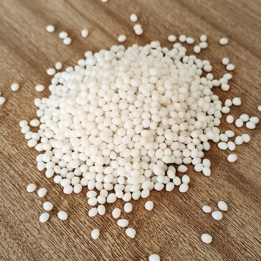
PA66 shrinkage is the reduction in size as nylon 66 cools and solidifies in molding. Warpage is a change in shape from uneven contraction or stress release. A low shrinkage value alone cannot predict a flat part.
Illustrative scenario: A housing meets its overall length requirement, yet its mating face rocks on the inspection plate. The length report answers a size question. It leaves the flatness question open.
When fit is at risk, changing pressure or cutting steel can feel urgent. First check what changed, in which direction, and in what part state. This guide explains how to read grade data, separate competing causes, and build a trial record that supports the next decision.
Key takeaways
- Read PA66 shrinkage values with the grade, direction, and test method.
- Measure feature size and form separately, using an agreed datum.
- Compare parts with matched inspection and exposure histories.
- Test a specific cause before changing the mold or material.
Start with the full material name. Use our PA66 material listings to identify the grade for a document inquiry.
Read PA66 shrinkage data by direction
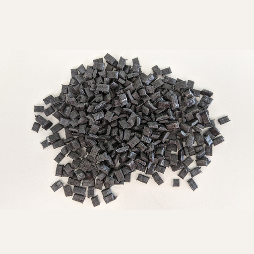
Parallel and normal are different measurements
Parallel means along melt flow in the test geometry; normal means across it. Neither label automatically means the longest or shortest edge of your part. Flow turns around cores and corners, so check the local direction first. Then match the feature to the datasheet value.
BASF’s September 2026 sheets provide a useful PA66 shrinkage comparison. The Ultramid A3K processing sheet and Ultramid A3EG6 product information, both page 2, report:
| Named grade | Direction or result | Value | Method or boundary |
|---|---|---|---|
| Ultramid A3K, PA66 | Parallel to flow | 1.50% | ISO 294-4 |
| Ultramid A3K, PA66 | Normal to flow | 1.80% | ISO 294-4 |
| Ultramid A3EG6, PA66-GF30 | Parallel to flow | 0.53% | ISO 294-4 |
| Ultramid A3EG6, PA66-GF30 | Normal to flow | 1.02% | ISO 294-4 |
| Ultramid A3K | Constrained, longitudinal | 0.95% | Centrally sprued model housing; conditions below |
| Ultramid A3EG6 | Constrained | 0.55% | Centrally gated test box; conditions below |
The glass-filled grade has lower values in both ISO directions, but a larger gap between directions. This explains why lower PA66 shrinkage need not mean less warpage. The numbers are producer document values, not tolerances or predictions for your housing.
Read each PA66 shrinkage row as a test result with limits. Ask whether the sheet reports a free specimen or a restrained box. Then mark the flow path on the part sketch.
If that path is unclear near a corner, keep the uncertainty visible rather than assigning the nearest datasheet percentage. A single linear feature cannot establish volume change.
Keep constrained PA66 shrinkage results separate
Both constrained examples use a base measuring 107 x 47 x 1.5 mm and a melt temperature of 290°C. The A3K example uses a mold temperature of 60°C; A3EG6 uses 80°C. The test conditions differ. These results do not isolate the effect of changing grades.
Don’t merge these values with the directional results or treat them as interchangeable tooling factors.
Illustrative calculation: With a 100.00 mm reference and a 99.40 mm specimen feature, linear reduction is (100.00 − 99.40) / 100.00 x 100 = 0.60%. These inputs are invented to explain the arithmetic. This is neither an ISO test report nor permission to enlarge a cavity by that amount.
MOCOM’s Altech PA66 processing guide, page 2, explains why shrinkage depends on filler, geometry, walls, mold design, and processing. For PA66 shrinkage comparisons, match those boundaries before judging grades. Record the sheet revision too; a familiar trade name is not enough to prove that two reports describe the same compound. The PA66 procurement guide covers full grade identification; GF30 alone does not establish fiber length or part fit.
Separate size change from shape change and later movement
Record form separately from PA66 shrinkage
A size report describes a feature between defined points. Flatness, bow, and twist describe form. Two edges can have the expected length while opposite corners sit at different heights. One PA66 shrinkage percentage cannot describe all these outcomes.
Record the drawing datum, measurement support, and whether the part is free or clamped. Clamping a bowed face flat may conceal the shape error you intended to measure. Compare the same feature in the same setup before deciding the resin or mold has changed.
Separate molding history from exposure history
PA66 shrinkage during molding differs from later size changes. The part contracts as it cools and its polymer forms crystals. More crystals may form later, and built-in stress may relax. Moisture uptake can also change size.
These effects need not cancel, and not every later size change is moisture.
BASF’s Ultramid technical brochure, printed pages 49–51, separates shrinkage, aftershrinkage, and warpage. This historical guide supports the mechanisms; use current grade documents for material-specific conditions.
Illustrative scenario: Press inspection and receiving inspection disagree about one housing. Before blaming moisture, compare sample identity, time since molding, temperature, packaging, and fixture use. Without those records, the reports may describe different states rather than a changing process.
Pellet drying controls the material entering the machine. Part conditioning concerns moisture in the molded article. Use the PA66 pellet drying guide for the feedstock baseline; a drying record does not prove the later part state.
Agree the acceptance state with the drawing owner. Avoid a universal waiting interval.
In a PA66 shrinkage dispute, retain the same sample labels through each check. Agree which state answers the drawing requirement before comparing the reports. This keeps a later exposure effect from being treated as a tooling error.
For visual context, this Kruse Training webinar introduces shrinkage and warpage interactions in injection molding; it is not a PA66 settings recipe.
Diagnose PA66 shrinkage and warpage in a controlled sequence
Establish a repeatable baseline
- Define the defect. Name the failing feature, direction, and drawing requirement. Record size and form separately. Mark the gate, cavity, and inspection points on a sketch.
- Lock the measurement. Check the gauge, datum, support, part temperature, and state. Check the same part again. If those results disagree, resolve the gauge or setup issue first.
- Verify material preparation. Record the full grade, lot, permitted regrind, handling, and moisture evidence. Compare the actual preparation with that grade’s current instructions. Don’t substitute a family-level drying rule.
- Stabilize filling and packing. Review fill pattern, transfer, cushion, hold pressure, and hold time. Use actual melt and mold measurements where available. A machine setpoint does not prove the state inside each cavity.
- Check cooling and release. Map opposite mold surfaces, coolant behavior, cooling time, and ejection. Inspect for sticking, drag, or uneven support while the part remains warm.
- Review flow and geometry. Compare the repeatable distortion with gate location, wall changes, ribs, and local flow direction. Take a stable pattern to the part and mold teams with the trial record.
This order keeps a PA66 shrinkage investigation from jumping between unrelated changes. Trained staff should follow the approved process limits and trial plan. Change one factor at a time, or use an approved designed experiment when interactions matter.
Use symptoms to choose a test
Use this matrix to choose a test. Appearance alone does not prove a cause. Choose the row that matches the evidence, then test its competing explanations.
| Symptom | Plausible causes | Discriminating check | Confounder | Next decision |
|---|---|---|---|---|
| One cavity drifts; others do not | Local packing, cooling, or measurement difference | Compare cavity-tagged parts and local conditions | Mixed cavity samples | Investigate that cavity before changing the whole process |
| All cavities drift together | Material preparation or shared process change | Compare lot, moisture evidence, fill history, and actual temperatures | Changed inspection state | Restore the baseline before assessing steel |
| Near-gate size differs from far-gate size | Pressure loss, early sealing, or local geometry | Study hold response and features along the flow path | Unequal walls | Review packing access and gate design |
| Bow differs across opposite walls | Cooling imbalance or uneven release | Map wall temperatures and ejection behavior | Fiber direction | Review cooling and restraint together |
| Twist follows a repeatable flow pattern | Directional contraction or geometry interaction | Compare form, local flow, and validated analysis | Unmatched part states | Review gate, walls, and material options |
| Shape changes at ejection | Sticking, release stress, or weak hot-part support | Observe release and compare handling | Later cooling movement | Review ejection and cooling before fixtures |
Interpret a gate-seal study carefully
Under an approved trial, vary hold time while controlling the other factors. A part-mass plateau can support an assessment of gate seal. Check feature dimensions and form alongside mass; equal weight does not prove equal cavity-pressure history, correct moisture, or acceptable fit.
RJG’s process-strategy article connects dimensions, packing, cavity data, and weight. Its examples use other polymers; their numerical results are not PA66 shrinkage data. Define stabilization and sampling rules before collecting results. Keep cavity identities separate and retain observations that contradict the leading hypothesis.
For PA66 shrinkage linked to packing, state the expected response before the trial. If mass changes but the failing feature does not, record both results. That finding weakens a simple packing explanation for that feature; it does not prove a different cause.
Choose process, mold or material changes from the evidence
When a process adjustment is justified
A process change needs a repeatable response, not just a better-looking sample. If a controlled packing trial changes the failing feature, record the response together with flash, other dimensions, and part form. More pressure may improve a local size while making another requirement harder to meet.
If cooling or release changes the bow, retain the actual temperature and handling records. Don’t label a longer cycle the cure until the agreed part state and functional checks support that conclusion. Process changes must remain within the grade and equipment limits.
When the mold or geometry needs review
Stable PA66 shrinkage offsets differ from run-to-run drift. A repeatable directional pattern under a controlled process may justify reviewing gate position, wall transitions, ribs, cooling layout, or restraint. A drifting baseline gives weak grounds for a steel change.
Illustrative scenario: A team considers another cavity recut after two runs give different dimensions. The next useful action is to compare their material, state, and process records. A single tool correction cannot be selected confidently from two unmatched baselines.
Simulation can help test a flow or orientation explanation. Its result depends on the material data and test assumptions. Ask which exact material card, gate model, and thermal inputs were used, then compare the predicted pattern with measured parts. A color plot alone does not validate a PA66 shrinkage allowance.
When a material change needs requalification
Reinforcement shape matters as well as loading. MOCOM describes smaller gaps between directions in Altech grades with plate-like fillers. Its guide also identifies glass-bead and mineral-filled options. These are candidates for review, not drop-in cures for a warped part.
Changing the compound can affect stiffness, impact behavior, weld lines, processing, and fit. Recheck the complete part requirements in the intended state. Neither adding glass nor choosing a lower PA66 shrinkage figure replaces qualification. A fixture may impose shape, but does not prove that stress, fit, or function will remain acceptable after release.
For a proposed alternative, compare the full incumbent and candidate designations first. Use our PA66 listings for a grade-document inquiry, stating the failing feature and required part state. Ask for current producer information before planning a material trial.
Document a dimensional trial before changing tool steel
Keep the feature and sample records together
A useful PA66 shrinkage report lets another team track the same feature from mold to gauge. Keep raw results as well as averages. An average can hide a cavity-specific problem or opposite changes in two directions.
Use the following record as a handoff template. It is an editorial investigation aid, not a certified test method. The responsible teams should add their own drawing and control-plan requirements.
| Record field | Why it matters | Responsible source or approval |
|---|---|---|
| Full grade, color, lot, preparation, and permitted regrind | Connects material identity to the run | Material and process teams |
| Part revision, cavity, gate sketch, sample ID | Prevents mixing designs or cavities | Tooling and production teams |
| Feature, direction, datum, fixture, gauge | Makes the size and form results comparable | Drawing owner and quality team |
| Time since molding, temperature, exposure, packaging | Defines the inspected state | Production and inspection teams |
| Actual process conditions, change, and stabilization record | Connects each sample to the trial | Process engineer |
| Individual sizes, flatness or twist, and mass where useful | Shows responses beyond an average | Quality team |
| Accepted limits, final decision, and remaining question | Defines the next action and its owner | Drawing owner and authorized reviewers |
The plastic pellet quality-control guide helps organize incoming lot evidence. A certificate of analysis records material identity or batch test results. It does not certify a finished housing’s size or shape.
Agree what ends the trial
Before starting, define which results would support a process correction, a mold review, or a material trial. Keep the sample count, inspection state, and acceptance limits under the approved plan. Don’t invent a universal flatness limit or capability index.
Return to the press-versus-receiving example: the PA66 shrinkage report needs to show whether the same parts were compared. PA66 shrinkage conclusions are only as clear as that chain of identity. If state histories remain unmatched, record that limit rather than declaring a root cause.
PA66 shrinkage questions engineers ask
These answers summarize the decisions above. Keep the exact grade and the feature that governs fit beside any quoted value.
What is the shrinkage rate of PA66?
There is no single PA66 shrinkage rate for every part. Producer values depend on the grade, direction, test geometry, and process. For example, the cited A3K sheet reports 1.50% parallel and 1.80% normal under ISO 294-4. Use such values to frame a trial, not as a universal tooling allowance.
Why can glass-filled PA66 shrink less yet warp more?
Glass fibers can reduce contraction along flow while leaving a larger difference across directions. Local orientation and geometry then influence shape. The cited A3EG6 values show lower contraction but a larger directional gap than A3K. This illustrates a mechanism; it does not predict that every glass-filled part will warp more.
Will more holding pressure always fix warpage?
No. Holding pressure can affect packing while the gate can still transmit pressure, but warpage can also involve cooling, orientation, geometry, and release. Check the feature response in a controlled trial. A heavier part or a better overall length does not prove that flatness or the final fit has improved.
Should PA66 dimensions be checked dry or conditioned?
Use the state specified by the drawing owner and application requirements. Dry and conditioned results answer different questions and should not be compared without their histories. Record time, temperature, exposure, and handling. Don’t choose a state solely because it makes the part pass, or assume a fixed waiting time defines it.
When should a mold be modified instead of the settings?
Consider mold changes when repeatable measurements under a controlled process point to a stable geometry, gating, or cooling constraint. First rule out mismatched inspection states and process drift. Review the affected features with the mold and part teams. Changing steel on an unstable baseline can leave the original uncertainty unresolved.
Prepare the next PA66 grade inquiry
Start with the feature that must fit. Read the directional data, separate size from form, match the inspection state, and test the cause that best fits the observations. A PA66 shrinkage figure is one input to that sequence, not the final decision.
For the opening housing, the missing evidence was its mating-face form and measurement setup. A PA66 shrinkage percentage alone could not answer that question. Your trial record should make the same gap visible before anyone chooses a permanent correction.
For a material inquiry, use the PA66 listing and inquiry path. Send the full grade, failing feature, directional results, intended part state, quantity, and destination. Ask for current producer documents and offer terms.
A precise PA66 shrinkage question helps the grade discussion. The agreed part trials and checks still govern final acceptance.