POM shrinkage needs a stated grade, direction and measurement condition. Separate cavity-to-part size change from warpage, then track how the same features move after that first check. One percentage cannot answer all three questions.
A part fits at the press but won’t fit at assembly. Before changing resin or cutting steel, ask what changed between those checks. Time, part temperature, support and exposure may differ, even when the drawing and tool have not changed.
Both checks can look valid. Yet they may describe different states of the same part. This guide shows how to compare them on equal terms, test likely causes and choose the evidence needed for a process, tool or grade change.
Key Takeaways
- State the measurement basis before using a mold shrinkage value.
- Check size and form separately; an acceptable length does not prove flatness.
- Record cavity, flow direction, time, temperature and support for each sample.
- Recheck exposed parts at the reference state before calling movement permanent.
Start with the complete material designation. Use the POM acetal pellets guide for procurement context, or browse the plastic pellet catalog when organizing a grade comparison. Keep current producer documents beside the trial record.
Set a shared reference state: the part temperature, time and support used for a fair check. Don’t let a quick press check silently become the basis for final tool approval.
Define POM Shrinkage Before Choosing a Compensation Factor
Distinguish size change, form error and later drift
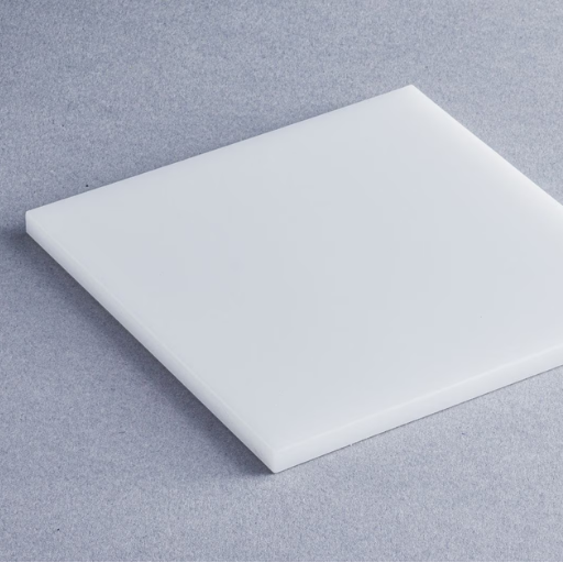
Mold shrinkage compares a cavity feature with the same feature on the molded part at a stated time and temperature. Warpage is a shape error: a plate bows, a frame twists or a sealing face no longer lies flat. A part can have both problems. One length check cannot show its whole shape.
Later movement adds a question. Did the same feature change after the first check? Compare like with like before blaming the resin. You can’t isolate time by checking a warm, unsupported part first and a cool, clamped part later.
POM is a semi-crystalline polymer. Its cooling and crystallization history affects dimensions, while packing and restraint also matter. The producer guides discuss these interacting effects; they do not reduce every finished part to one material constant.
Show the denominator and the test basis
For a simple linear comparison, this article uses:
Linear shrinkage (%) = (cavity length − part length) / cavity length × 100.
An illustrative cavity length of 100.00 mm and part length of 98.00 mm give 2.00%. These invented values show the math; they are not POM test data or a tool allowance. Record the state of both lengths. Use the definition required by the test method.
With this denominator, the inverse relation is cavity length = target part length / (1 − shrinkage fraction). A 2.00% fraction would be 0.0200, not 2.00, in that expression. Do not select that value from this example.
First establish the relevant grade, feature and trial basis. The decimal places shown here do not set an instrument resolution or part tolerance.
The Celcon processing guide, Chapter 3, reports 1.2–2.4% for standard unfilled products on laboratory specimens. It also notes an actual-part observation as high as 3.7%. Those figures illustrate why a laboratory range is not a cavity design instruction. They do not establish a universal minimum, maximum or tolerance for POM.
The Delrin guide gives a similar warning about scope: its cited shrinkage study used standard 2 mm bars and recommended conditions for Delrin 500P. A different geometry, grade or molding history needs its own evidence.
Check data along the flow and across it separately. Reinforcement can change how the two directions compare. Read the grade and specimen notes before using a chart.
Illustrative scenario: A buyer receives an early press measurement and a smaller dimension from inspection later. The team first aligns part temperature, elapsed time and fixture use. That comparison can identify a genuine difference to investigate; the two original readings alone cannot establish its cause or the correct steel allowance.
Measure POM Shrinkage and Warpage by Time, Direction and Cavity
Establish a repeatable reference state
Choose the critical features from the drawing before collecting samples. Identify length, width, hole spacing and any form requirement that affects assembly. State the datum, meaning the reference used to locate the part. Decide whether the drawing calls for a free-state or restrained check.
Record the gauge and fixture so another person can repeat the check. A fixture can hide bow by pressing a part flat. A loose part may also sit in a different way each time. Don’t change supports during a trial and call the resulting difference material movement.
Keep the cavity label attached to each part. Combining cavities can hide a local issue. Mark directions on a sketch; not every feature lies along the main flow path. Make sure a label or mark does not interfere with the surface being checked.
Build a dimensional record that survives handoffs
Use the following blank record as a starting point. Complete it with actual trial data; it is not a test specification or a completed inspection sheet.
| Record group | Fields to complete | Question it answers |
|---|---|---|
| Material | Producer, full grade, lot, color and regrind history | Did the material basis change? |
| Tool and sample | Tool revision, cavity, shot/sample identity | Are the same populations compared? |
| Feature | Drawing revision, datum, direction and form limit | What exactly must fit? |
| Measurement | Instrument, fixture, support and operator | Can the check be repeated? |
| State | Time since molding, part temperature and storage | Are the states comparable? |
| Exposure | Heat, moisture, load and restraint history | What happened between checks? |
At each handoff, check these details:
- Match the sample label to the cavity and trial condition.
- Note startup or restart status, not just the stored recipe.
- Keep each reading before calculating a cavity average.
- Record failed readings and any reason for excluding a sample.
An average inside the limits can still hide a cavity that needs work. If clamping is required, record how the part is held. The next inspector should not have to guess the force or seating method.
Set the measurement times in advance. Celcon’s guide recommends room-temperature conditioning for at least 24 hours, preferably 48 hours, before critical measurement and tool adjustment in its trial procedure. Treat this as that manual’s recommendation. It does not prove that every POM part stops changing after 48 hours or meets its service requirement.
Agree the sampling and acceptance rules with the responsible quality and tooling team. The number of parts and timing must fit the drawing, process risk and applicable requirements. This guide does not supply a universal sample size.
Before changing settings, repeat the check using the same method. If the check can’t separate a claimed gain from normal gauge variation, the trial doesn’t support that claim. Resolve the method first. Then compare process conditions.
Diagnose Uneven Packing, Cooling and Ejection Without Guessing
Let the pattern select the comparison
Start with where the defect occurs and when it appears. A repeatable difference between cavities needs a different test from drift in all cavities after storage. Neither pattern proves a cause. Use it to choose what to check next.
The Celcon guide identifies wall thickness, gate details, molding conditions and filler orientation among the factors affecting shrinkage or warpage. Use the drawing and tool checks to choose a cause to test. If you change heat, pressure and time at once, you won’t know which change mattered.
Write the expected response before running the trial. Keep the sample groups separate and record when the process has settled.
| Observed pattern | Hypothesis to test | Controlled comparison | Limit on the conclusion |
|---|---|---|---|
| One cavity bows more | Local thermal or ejection difference | Compare surface temperatures, support and ejection behavior by cavity | A shared coolant setpoint does not prove equal surfaces |
| Size and mass vary together | Packing or feed-path variation | Track weight, dimensions and available pressure data at stable conditions | Stable mass does not prove acceptable internal quality |
| Form changes after handling | Uneven cooling or restraint outside the tool | Compare an agreed handling method with the baseline | A new method must still satisfy production and quality needs |
| A change alters one direction more | Flow, geometry or filler effects | Compare marked features in both directions | A single overall shrinkage factor hides direction |
Interpret weight, pressure and temperature together
Part weight can help show how feeding changes during packing. It can’t prove that size, flatness or internal quality pass. Check the required features as well. A full sink-and-void study is a separate task; don’t use weight alone to close it.
Delrin’s molding tips explain the link between adequate packing, gate design and dimensional precision. Its illustrated test part achieved better precision with optimized packing and limited additional cooling. That example challenges the assumption that longer in-mold cooling always reduces warp.
It isn’t a rule to eject every POM part early. The gate, part shape and ability to leave the tool without damage still need review.
Look beyond the machine screen. Check the feed path, tool surfaces and how the part leaves the mold. Stay within the current grade guide and approved process limits. A shorter cycle isn’t a fix if it damages the part or shifts the error elsewhere.
Illustrative scenario: Two cavities make the same frame, but one frame rocks on the inspection surface. The team compares cavity identity, temperature pattern, ejection and handling while keeping the measurement method fixed. The result to seek is repeatable evidence, not an assumed cooling diagnosis. No customer result or measured improvement is implied here.
If a grade change becomes a serious option, use the engineering plastic selection framework to review the wider requirements. Changing material can affect more than dimensions. Do not use a grade substitution to conceal an unresolved tool or measurement problem.
Separate Post-Mold Shrinkage from Reversible or Exposure-Driven Movement
Keep the temperature and exposure history visible
A later size change needs a time and a state. The Delrin technical molding guide, printed page 34, defines post-molding shrinkage as reduction occurring more than 24 hours after molding. It links the effect to continued crystallization and relaxation of molded-in stresses. That is a producer convention, not a physical switch at the end of the first day.
Separate lasting drift from size change that reverses with temperature. Check after an agreed exposure, then check again at the original part temperature with the same support. A hot reading includes a heat effect. It doesn’t, on its own, show how much change will remain when the part cools.
The Celcon manual also discusses size change from moisture absorption. A low moisture response is not zero response. Record storage and exposure when they matter to the drawing or use of the part. Do not assign every later change to further crystallization before checking other causes.
If the project also considers nylon, the separate PA66 shrinkage and warpage guide provides a different-material comparison. PA66 conditioning requirements are not a POM procedure. Transfer the discipline of recording material state, not nylon’s conditioning assumptions or numerical values.
Decide on annealing before the final tool correction
Annealing means a controlled heat treatment. It can change dimensions and may cause distortion; it is not a guaranteed rescue for an unstable process. Celcon advises making the annealing decision during planning, before final cavity and core sizing. Delrin also warns about deformation when trying to stabilize parts molded under unsuitable conditions.
Don’t take a temperature or time from a generic article and use it for an unknown grade. Get the producer’s applicable procedure. Agree the purpose, support, cooling and pass criteria. A heat test used to find a cause doesn’t prove performance over the part’s service life.
Illustrative scenario: A team measures a part, applies an agreed heat exposure, then measures it again after return to the original reference state. It also records restraint during exposure. Any remaining difference can now be investigated without mixing a hot reading with a cool baseline. This example defines a comparison, not an accelerated-life test or a predicted outcome.
Agree that exposure plan with the responsible team before accepting a fix. State which size and form limits must pass afterward. Label the exposed samples and unexposed reference group so a reviewer can follow the decision.
Record any load or restraint used during the test. Check the same features again; a new feature cannot stand in for the original failed one.
Release a Dimensional Record Before Changing Grade or Tool Steel
Match each action to its evidence
Do not cut steel around incompatible measurements. First collect the drawing state, exact-grade documents, lot record, process history and cavity-specific dimensions. Keep form results beside size results. A simulation can help select a trial, but it does not replace physical acceptance measurements.
Separate pellet release from molded-part approval. A certificate of analysis can describe the supplied material against its stated tests; it does not demonstrate that your tool and process produce an acceptable part. The plastic pellet quality-control guide explains this procurement-versus-part distinction.
Use the evidence to choose a next action:
- Continue investigation: resolve inconsistent methods, missing state records or unclear cavity identity before choosing a correction.
- Correct the process: show a repeatable response within approved bounds, then recheck size, form and other required quality features.
- Review the tool: bring a stable process and repeatable feature error to the tool owner; include the affected cavity and direction.
- Requalify the material: document why the current grade cannot meet the combined requirements and test the proposed alternative.
- Release the part: obtain the required approvals against the agreed drawing, measurement states and exposure conditions.
These are decision branches, not a promise that every investigation ends with a process fix. A repeatable result still needs the agreed pass criteria. Check what passed, in which state and under whose approval. If no action has met those criteria, keep the issue open rather than describing a trial as a validated correction.
Keep requalification triggers explicit
Name who approves a change and what must be repeated afterward. Review a new lot, color package, regrind practice, storage condition or service exposure against the qualification basis. A restart also needs the checks defined by the approved control plan. Do not assume every change requires an identical test program.
Close the exposure scenario by attaching its before-and-after record, not just a statement that the part was heated. Retain the failed trials too. They explain why the team rejected an apparent shortcut and help prevent a future shift from repeating it.
The release record should let a buyer, process engineer and tool owner reach the same understanding of what was tested. If one person cannot reconstruct the grade, feature, state and approval basis, fill that gap before committing to a material order or steel change.
POM Shrinkage and Warpage Questions
What is the shrinkage rate of POM?
No single rate safely describes every grade and part. Start with the exact-grade datasheet, test method and flow or transverse direction. Then check your tool and process.
Producer lab values are useful references. They don’t replace part-specific checks or establish the final cavity allowance.
How long should I wait before measuring a POM part?
Follow the agreed inspection method and grade guide. Celcon’s trial procedure recommends at least 24 hours, preferably 48 hours, at room temperature before critical checks. This doesn’t prove that all movement has ended. Record elapsed time and check any later exposure at the same reference state.
Why can a POM part meet size limits but still warp?
Size and form are different requirements. A frame can meet a length limit while one corner lifts from its reference plane. Check the drawing’s datum and form limits as well as length. Record whether the part is free or restrained; clamping it flat can hide the shape problem.
Will longer cooling or higher holding pressure fix warpage?
Neither change is a universal fix. The response depends on packing, feed path, shape, cooling and restraint. Run a controlled test within approved grade and process limits.
Check size, form and other required quality features together. A better weight reading or one flatter sample doesn’t prove a repeatable fix.
Does annealing prevent later dimensional movement?
Annealing can change size and may distort a part, so plan it with producer guidance. Define the purpose, support, cooling and pass criteria before the final tool correction. Don’t assume heat treatment guarantees stable size in every service environment. Recheck the relevant features at the agreed reference state.
Next action: For the next material discussion, bring the full grade code, current producer documents and completed dimensional record. Include the drawing revision, affected cavity, measurement state and exposure history. If alternatives need review, browse the plastic pellet catalog alongside those requirements.
Choose the next trial from what is missing in that record. If the data don’t yet support a change, keep the issue open. Match the material and process to the part’s pass criteria instead of choosing one shrinkage percentage for every feature.