
Review POM gate and vent design by tracing two connected paths: where melt feeds the part and where displaced air leaves the mold. Compare the actual tool with the exact resin grade’s guidance before choosing another process change.
A part can look full while a narrow feed path limits packing or a final air pocket has no useful exit. If each shift changes speed, heat and pressure without a shared record, the next trial starts with another guess. A tooling review gives the team a drawing, measured features and observations to discuss.
Use the POM grade and procurement guide to assemble the material documents. This review then connects gate position, restrictions and vent condition to a controlled next action. It does not assume that every defect requires cutting steel.
Key Takeaways
- Match the complete grade code and tool revision to the last accepted baseline.
- Follow the whole packing path, including thin sections between the gate and heavy features.
- Trace each relevant vent through its shallow land, relief and outlet.
- Approve changes using cavity-labelled parts and defined acceptance checks.
For a later material comparison, browse the plastic pellet catalog with your grade code and drawing requirements at hand.
Define the POM Gate and Vent Design Review
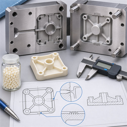
Identify the material and drawing
Start with the full grade code, including its suffix, color and any modification. A label saying only “acetal” does not tell you which processing guide to use. The POM homopolymer and copolymer comparison explains the separate material-selection question. A family name can’t approve a gate detail for every grade.
Ask which resin designation and tool drawing produced the last accepted parts. Record the material lot and the drawing revision used for the current trial. If the drawing and physical tool differ, flag the discrepancy for the tool owner. Don’t quietly treat the drawing as an inspection result.
Use a review cover sheet that separates documents from observations:
| Review item | Record to attach | Responsible role |
|---|---|---|
| Material identity | Full grade, lot, color and current processing sheet | Material owner |
| Tool identity | Drawing revision, cavity IDs and gate arrangement | Tool owner |
| Actual geometry | Measured gate, runner and relevant vent features | Qualified inspector |
| Process baseline | Approved setup and actual machine response | Process engineer |
| Part acceptance | Drawing limits, appearance and functional requirements | Quality owner |
Leave unknown fields open and name who will check them. If you haven’t measured a feature, inspect it. Don’t assume it meets a general ratio.
Agree what the review must decide
Mark load-bearing areas, cosmetic surfaces and dimensions that matter in service. Agree how to check the part. Name who can approve cleaning, a trial or a tool change. Each action needs its own evidence and owner.
Illustrative scenario: An inherited tool arrives with a drawing associated with an earlier resin designation. The team first reconciles the resin record, drawing and installed inserts. Applying a gate-size rule before that check could answer the wrong design question. No production result is implied by this example.
Prepare the current producer processing sheet, safety data sheet and actual tool drawing together. The review should end with a specific inspection or trial decision, not a general instruction to make the resin flow more easily.
Place the Gate Around Packing and Air Escape
Follow the packing path
Packing feeds additional material into the cavity as the part solidifies and contracts. The gate and connecting sections must remain usable for that feed to reach the intended feature. A gate beside a heavy section is not enough if material must pass through a narrower section to reach another heavy area.
The Delrin Technical Molding Guide, pages 11–12, connects gate placement with packing access and avoidance of flow bottlenecks. Use that principle to annotate the drawing. Mark the gate, changing wall sections, long flow paths and regions whose feeding may end early.
Trace the path through the part and mark:
- Thin bridges or reduced sections ahead of heavy features.
- Rib junctions where the flow changes direction.
- Features far from the gate that still need feeding.
A fill sample shows where material travels. Later checks must show whether the heavy feature meets its requirements.
Gate location also affects how melt enters the cavity. Directing flow against a wall or core can reduce jetting, where an entering strand travels freely before spreading. This is a geometry consideration, not a guarantee of a clean surface. Review the resulting flow pattern and appearance on the actual part.
Keep the gate region and predicted weld lines away from highly stressed service areas where feasible. A weld line is the meeting region of separate melt fronts. Its location matters even when it is hard to see. Appearance alone cannot establish its strength.
Predict the last air pocket
Draw the expected flow fronts and ask where the final displaced air can leave. A convenient gate location may move the final pocket into a region with no usable vent path. Include cores, blind ends and features where fronts meet in that review.
Illustrative scenario: Compare side entry with entry at the center of a hypothetical sleeve’s closed end. The Delrin guide uses a closed-end tube to show how gate position changes air displacement. Central closed-end entry can direct air toward the open-end parting line; side entry can trap air near the opposite closed-end region. The installed tool still needs its own assessment and trial.
An edge or fan gate, a pin or tunnel gate, and direct or indirect entry bring different access and removal constraints. Include acceptable gate vestige, the remnant after separation, and access for degating in the drawing review. Choosing an easily removed gate must still leave a workable feed path.
Keep later size and shape changes in the POM shrinkage and warpage investigation. Before asking about a gate move, mark likely weld lines, final-fill regions and vent exits on this drawing.
Review Gate Size, Land and Runner Restrictions
Compare like dimensions
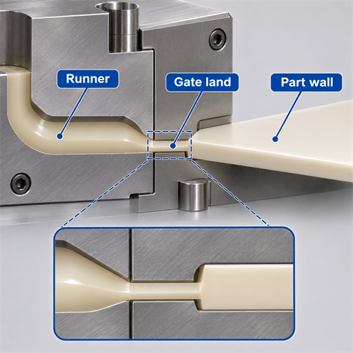
Gate thickness or diameter influences when the gate freezes and stops transmitting packing pressure. A small opening can restrict feeding; enlarging it also changes separation forces and the visible remnant. Gate land means the short passage through the gate. Keep it distinct from the shallow land through which a vent releases air.
Producer recommendations use different shapes and wall references. The following values describe the cited guides’ scope. They are reference points for review, not a drawing approval for an unspecified POM grade.
| Producer guidance | Dimension and stated reference | Review boundary |
|---|---|---|
| Delrin molding guide, p12 | Gate thickness or diameter: 50–75% of wall thickness at the gate | Preserve the local-wall reference and gate shape |
| Delrin molding guide, p12 | Gate width at least equal to gate thickness; gate length no more than 0.8 mm | Width and length describe separate gate features |
| Celcon processing guide, p4-6 | Smaller edge-gate dimension: one-half to two-thirds of maximum part wall thickness | Applies to the edge-gate discussion and its maximum-wall reference |
| Celcon processing guide, p4-6 | Round-gate minimum recommended diameter: 0.76 mm, with preference above 1.52 mm | The guide also notes smaller successful exceptions; this is not an all-POM minimum |
The Celcon Acetal Copolymer Processing and Troubleshooting Guide supplies the Celcon entries. Do not average these ratios. First identify the dimension, gate shape and wall reference; then ask whether the current producer guidance supports that feature in this tool.
Check the restriction before the gate
Inspect upstream runners, transitions and the route to each cavity. An acceptable gate opening does not clear an undersized feed branch or a restriction near the nozzle. Include the cold-slug capture feature, which intercepts cooled material before it reaches the part, where the system design calls for it.
Use one inspection row per feature:
- Cavity and feature: ____
- Drawing value and revision: ____
- Measured value and method: ____
- Owner and approved next action: ____
Leave results blank until measured. A value on a drawing is not proof of the size in the tool. Also note wear or damage that a single dimension might miss. Keep a photo or inspection sketch tied to the same feature ID.
For tunnel arrangements, distinguish the tunnel section from the final gate opening. The Delrin hot-runner guide’s pictured cold-sub-runner design specifies a tunnel diameter beside the gate of at least 1.2 times part thickness. That statement does not describe the final gate diameter or every tunnel layout.
A geometry discrepancy can justify tool-owner review. Matching geometry still leaves actual freeze-off and part quality to be checked. Use the grade-specific POM molding window for the fuller process trial, while keeping this worksheet focused on the physical restriction and its approved disposition.
Trace the Vent From the Cavity to Atmosphere
Find the final-fill and weld-line regions
Vents must let air leave the regions that fill last. Mark them on the drawing. Compare those locations with fill samples labelled by cavity.
Include pockets near cores and places where melt fronts meet. Also review runner venting where the feed system requires it.
The Delrin molding guide, pages 15–16, warns that poor venting may produce subtle or whitish marks rather than an obvious dark burn. This advice concerns Delrin. A clean surface doesn’t prove that air can escape. A mark alone doesn’t tell you its cause.
Illustrative scenario: An end-of-fill blemish repeats in one cavity while neighboring cavities look different. Retain labelled samples and compare the corresponding gate and air-escape routes. The pattern gives the team a location to investigate. It does not prove a resin defect, a blocked vent or a successful remedy.
Inspect the complete escape route
Follow the route from the cavity across the shallow vent land into the relief channel and through the outlet. A vent visible at the parting line may still have a restricted path farther downstream. Check the relevant pin or insert clearances only where they form part of the intended vent design.
The same Delrin guide gives a vent-land length no greater than 1 mm. This refers to the land length, not vent depth. The appropriate depth and other dimensions require the applicable material and tool guidance; copying a depth from another mold can introduce flash or leave poor evacuation unresolved.
Use an inspection record that preserves each part of the path:
| Feature | Inspection field | Decision field |
|---|---|---|
| Cavity and final-fill region | Cavity ID, sample reference and drawing location | Is the planned vent in the relevant region? |
| Shallow land | Approved drawing basis and measured condition | Does the tool owner need to assess a deviation? |
| Relief and outlet | Continuity, condition and observed obstruction | Is approved cleaning or repair needed? |
| Pin or insert path | Intended route and actual condition | Does it match the designed escape route? |
Ask qualified personnel to inspect and record the paths using the site’s approved procedures. Separate cleaning an existing passage from modifying its steel. A change in depth, land or outlet geometry needs its own authorization and subsequent checks.
After intervention, retain the inspection record and repeat the relevant observations under a documented baseline. Do not treat a brighter surface as the only acceptance test. The fill pattern, flash condition and required part checks still matter. The record should show what changed in the path and how the part responded.
Use Trial Evidence to Approve the Next Change
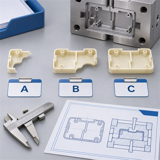
Match the observation to the next action
Agree a limited comparison with the process and quality owners. Record the start, planned change and settings kept fixed. If you change the gate, speed and holding pressure together, you can’t tell which change caused the response.
Progressive-fill observations under an approved trial procedure can help locate flow fronts and final-fill regions. Record cavity identity and the actual machine response. A pressure limit is a ceiling, not a measurement of pressure throughout filling. Likewise, commanded injection speed does not establish that the machine achieved it.
Use a decision table to keep conclusions proportionate:
| Observation | Next investigation | Evidence still needed |
|---|---|---|
| Repeated final-fill problem in one cavity | Compare its feed and vent paths with the drawing and other cavities | Measured condition and controlled trial |
| Gate differs from the approved drawing | Refer the discrepancy to the tool owner | Authorized disposition and part recheck |
| Part mass stops changing in a trial | Record the tested mass response | Required internal-quality, dimensional and functional checks |
| Appearance improves after cleaning | Document the cleaned route and repeat the baseline | Repeatability and full acceptance results |
A part-mass plateau alone doesn’t prove that a part has no voids or that its weld lines are strong enough. Choose checks from the drawing and service needs. Measure parts in the same defined state. Later shrinkage can otherwise hide the effect of a tool change.
Release the changed tool and process together
For a hot runner, review the nozzle arrangement, insulation, thermal balance and areas where material may remain too long. The Delrin Hot Runner Guide, pages 2–4, recommends indirect gating with a cold sub-runner where possible and also discusses direct-gating options. The broader molding manual is more restrictive about direct gating. These documents do not approve an individual system; ask the producer which current guidance applies to the exact grade and tool.
Review the actual resin and system with the producer and hot-runner specialists. Check when the gate freezes, where melt can remain too long and how heat is controlled near the nozzle. A blanket yes or no for all acetal misses those design conditions.
Before release, attach the revised drawing, approved change, trial setup and accepted part results by cavity. Record who approved the tool and process. State what the next shift must reproduce. Inspecting a feature does not by itself release the production setup.
For the material handoff, browse the plastic pellet catalog with the full grade designation, current producer documents and application requirements. Keep any later grade substitution within its own qualification process. A different material should not serve as an undocumented workaround for an unresolved tool feature.
Questions About POM Gate and Vent Design
How large should a POM gate be?
Use guidance for the actual material and gate shape, then compare the measured tool with the approved drawing. The Delrin and Celcon references above use different dimensions and wall references. Their ratios cannot be combined into one universal size. Actual feeding, gate separation and part acceptance still require verification.
Where should POM mold vents go?
Review final-fill regions, trapped pockets and places where melt fronts meet. The intended vent must connect those regions to a usable route out of the mold. Check the shallow land, relief and outlet together. A vent drawn elsewhere on the tool does not establish that the relevant pocket can empty.
Can faster injection fix poor venting?
Changing speed can change the fill pattern and visible symptom, but it does not establish that a restricted air path is adequate. Compare actual filling behavior with the intended escape route. Have qualified staff inspect that route and use an approved trial to evaluate any process change within the grade’s guidance.
Does a full-looking POM part prove adequate packing and venting?
No. A filled outline establishes only the observed external shape. It does not prove adequate feeding of heavy sections, internal soundness or weld-line strength. Define the dimensional, internal-quality and functional checks needed for the application. Even a stable part-mass result cannot replace those separate acceptance requirements.
Can POM be molded with a hot runner?
Suitability depends on the resin grade and the complete hot-runner design. Delrin’s dedicated guide discusses indirect and direct arrangements, with attention to thermal control and material stagnation. Review the actual nozzle, feed path and operating conditions with the responsible specialists. A broad acetal recommendation cannot approve an individual system.
Carry the completed record into the next review. It should show where melt must feed, where air must leave and what supports the next approved action.
If that review leads to a material discussion, browse the pellet catalog with the complete grade code and current documents. Keep the tool and material decisions traceable.